
I recently got a lot of responses about my use of a pinhole camera as a lab to introduce functions and curve fitting during Unit 0, Scientific Reasoning in modeling instruction.
Here’s my original post:
As another introductory lab for the scientific reasoning unit, I made some pinhole cameras from two boxes that could telescope inside each other so students could adjust the distance from screen to the hole. Students think the camera is cool, so it’s a memorable lab, you can get linear, inverse, squared and inverse square curves from the data, depending on how far you want to go with it, and the meaning of the trends relates to directly observable sizes of the object or the image. To get the squared fits, you find the area of the image by box counting, which reviewed the concept of area. All of this proved very useful later in the year, as they actually remembered the lab, and could think about whether sizes were increasing or decreasing to help recall the association between graph shape, equation and meaning.
I used the circle lab as a follow-up, and I still like it, but the students just don’t tend to remember it as well. Other labs such as the pendulum or a bouncing ball are memorable, but the relationships are more abstract and the students don’t seem to hold on to the visual picture of them as long, so they weren’t as good of a recall aid.
And here are more details:
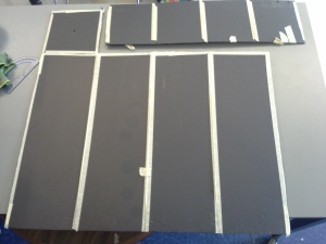
Building Plans: I built the cameras out of black foam core I got at the office supply store.

Material
black foam core 30”x40”
Outer box
L = 57cm
W = 19cm
Inner box
w = 17cm
Cuts
With a box cutter, cut all the way through to separate the outer and inner boxes. Score the other lines leaving the bottom paper/cardboard surface in place to hold it together. Bend and tape to form a box. I taped all of the edges for extra support, even though I left one layer of paper on most of them.
For the screen, I used 1/4” ruled vellum from Dick Blick.
Here are some photographs of a camera already cut out and ready to fold, and then completed.
 |
 |
|---|---|
 |
 |
For an image, I projected a cartoon of an elephant onto the screen at the front of my room and turned out the room lights. Everyone pointed their camera at the same object. Having the object on a screen and the image on another screen created some confusingly redundant language, so when I do it again, I’ll use an actual object outlined with lights. Maybe I’ll use a string of white LED Christmas lights and let the students tape it to a whiteboard in the shape of an animal of their choice. I want the object to be some irregular shape, though, so that it is easiest to get the area by counting boxes instead of calculating.
Update August 2017 – Light bulb for object, cheaper and better screen
We just got done with this lab this year. Thanks to my colleague, Rachel Atay, we made some improvements to the screen and decided on a bare light bulb for the object and it worked well. Any incandescent or LED bulb that was bright enough worked fine, so long as it was frosted and bulb shaped so that it made an irregular shape on the screen. We ordered some of these sockets, which plugged right into a power strip at each lab station – inexpensive and easy. 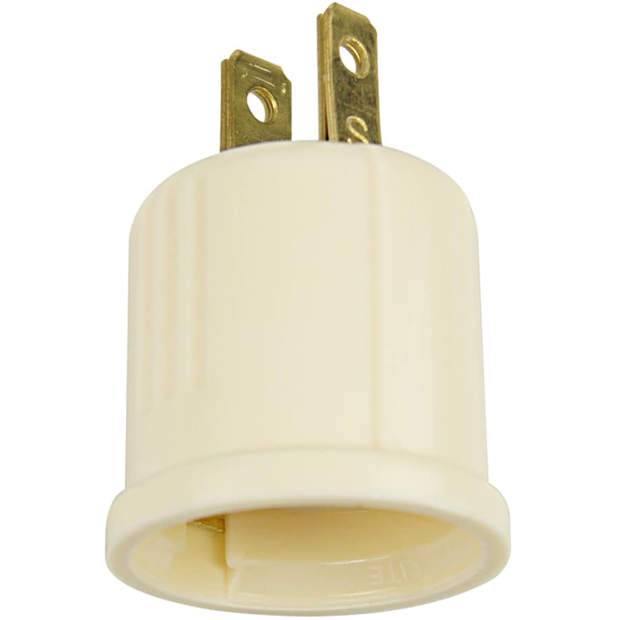
For screens, we got some tracing paper at Staples and traced a cm grid onto it. It is thinner than the velum we were using before so the image is brighter, the grid lines are darker, and they are more closely spaced. This all made it easier for the students to take good data, and the tracing paper was available locally and a lot less expensive.
Results
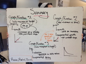 Here is a whiteboard with results from one student group. Note the independent variable and dependent variable and resulting graph shape and equation for each experiment. I did not try to combine the results into a single equation or derive it using similar triangles and ray tracing, as my objective was just to introduce and practice experimental design (identifying the IVs and DVs in the pre-lab discussion), data-taking and curve fitting.
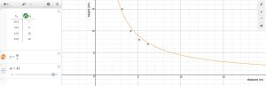
Here is some sample data from another student group and their graphs from Desmos.


I received this from Donna Richardson via the modeling list serve
If you’re thinking of making pinhole cameras to use this fall, I recommend Matt Greenwolfe’s blog for directions (He posted here on June 5), but I would suggest going to Staples or Office Depot and buying vellum in the area where they sell special printer papers (the stuff is sold for people who want to make fancy wedding invitations or something). It’s about half the price of the vellum at Dick Blick’s, much sturdier than tissue paper (which wasn’t working out for a variety of reasons, though if you look online you can find tissue paper with a grid on it, and that just might work). I like the vellum because I can print graph paper with whatever resolution I want to use on it (I used 0.2 cm grid with darker lines every cm). I have a crappy printer, so I had to tape the vellum to a regular piece of paper to get it to work (otherwise it would slide through much faster than the printer thought it should; the stuff is pretty slippery), but once I figured that out I had no trouble. With the grid I used, it is easy to measure image dimension with 2 sig figs.
I also had much better luck using cheap LED flashlights than I did using Christmas tree lights — the LED’s are pretty directional, and I would have about 3 dots show up from a many-LED shape. An LED flashlight has its LED’s planted in the same direction, and its reflector helps widen the range of angles you can see it from. With 3 LED flashlights, I could only make a boring triangle, but that is enough to show that the image inverts, and you can easily measure its width and height on the screen, then calculate its area. The flashlights are bright enough that you can see their dots if the room lights are off but without going to extremes to keep light from the hallway out. (In fact when image distance is large, you can see all 6 LED’s in a circle, forming a large dot) Keeping a constant object distance and varying the image distance I got an almost perfect direct proportion for length and width vs image distance, and an almost x-squared relationship for area vs image distance.
Donna Richardson
how do you get the area? a group of us got together and built the camera (success!), but when trying to take the area, we can’t see the grid inside the box. any tips?
When I did this, I was using a cartoon of an elephant projected onto a screen from my computer. It was probably brighter, and so the grid was illuminated. That created some language problems because the object was on a screen, and then there was a screen inside the camera. In my blog post, I suggested switching to a luminous object of some sort that was not on a screen, but haven’t had a chance to try anything out yet.
ok. we tried a couple of different things. We set up three Maglites in the shape of a triangle and got the image that way, and also projected an image on the Smart board to take measurements. Both ways we found were rather difficult to still see the grid. We ended up drawing on the vellum and then taking measurements. I think I will blog about it and will definitely tag you, or link to you (whatever the proper term is), so you can see the pics of what we came up with.
Thanks so much for the quick response!
Definitely an issue that needs to be worked out regarding how to do this best. I won’t be returning to get the equipment back out and test ideas until August, so looking forward to see what you figure out.
I really like this idea and am going to try it in September.
If you have some mailing tubes of different diameters laying around, they can also be used to quickly and cheaply build a pinhole camera that will work for this lab. Aluminum foil secured with a rubber band can be used for the pinhole end and then the vellum can be used for the screen and is attached to the tube with the smaller diameter. See this teacher’s blog for more information: http://pascals-puppy.blogspot.com/2010/04/pinhole-camera.html
I have also had some difficulty with insufficient brightness. I am going to try making a strange-shaped object with this inexpensive strip of LED lights: https://www.amazon.com/Flexible-Non-waterproof-Christmas-Decoration-Daylight/dp/B00HSF65MC I’ll let you know if it works or doesn’t work – they should be delivered in a few days.
Thanks for sharing.
Grant Cox
Bethel High School, CT
Hi Grant,
Those Christmas lights look promising. Let us know if they work!
Matt
We just did this lab for this year, and I updated the instructions above with some improvements by my colleague, Rachel Atay. We used a bare light bulb for an object and tracing paper for the screens – both less expensive and better.
In the post COVID-19 world of possibly starting the upcoming school year remote (or at least practicing social distancing of 6 ft’) I have created a Pinhole Camera Simulation Lab based on this lab. It is done in MS Excel w/ VBA – I have only tested on a windows machine. If anyone would like a copy email me at cmcdonald@davidsonday.org. I’d especially love feedback from Mac users!